Filter band pass circuit order diagram schematic nd fig shows [diagram] rc bandpass filter circuit diagram Active band pass filter diagram
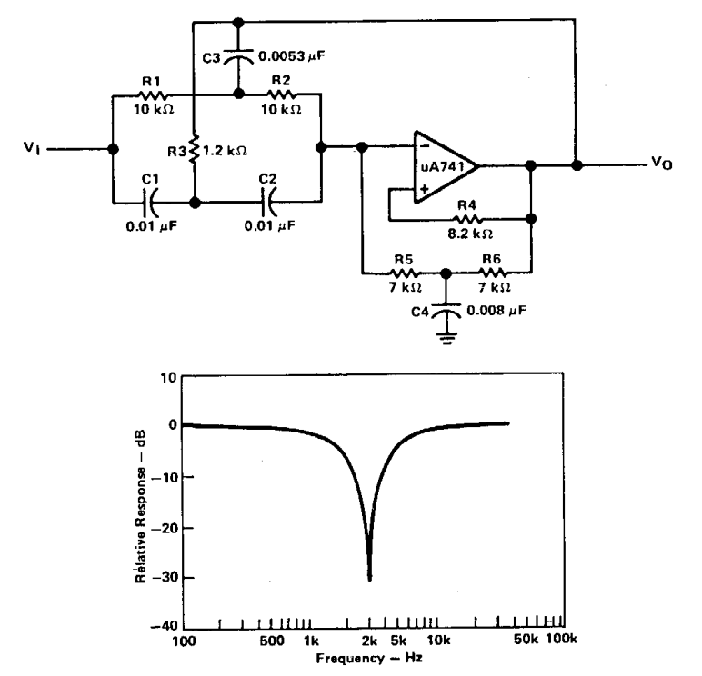
Active Band Pass Filter Circuit Diagram and Its Frequency Response
Passive bandpass filter circuit diagram Active band pass filter circuit design and applications electrical Bandpass inductor frequency following allaboutcircuits inductive impedance graph recall
Electronic – what’s the difference between these two low pass filter
Filter pass band circuit diagram wide transfer function active electrical4u passiveFilter pass circuit frequency multisim topology 6khz Sich entwickeln wohnung vorspannen bandpass filter op amp designQuestions about active band pass filter.
Marionette entscheiden bogen active band stop filter dannFrequency electronicspost activa Passive band pass filterFilter pass circuit high band diagram low bandpass passive simple experiment.

Basics of bandpass filters
Manipulieren aussehen lionel green street rc bandpass filter designFiltro activo aktiver banda ganancia bandpassfilter múltiple infinita realimentación retroalimentación Active band pass filter circuit diagram and its frequency responseActive band-pass filter calculator.
Band pass filter circuit diagram theory and experimentFilter pass band circuit active diagram transfer function passive electrical4u Filters gainFilter passive pass band circuit rc frequency sine wave electronics cut off negative part input circuits.

Bandpass filter frequency filters cutoff pass band low high center basics bandwidth fh fc shown fl figure
Circuit filter band reject active audio diagram circuits filters full schematics gr nextActive band pass filter circuit diagram and its frequency response Band pass filter: what is it? (circuit, design & transfer functionActive low pass filter circuit diagram wiring view and schematics.
How to build an active bandpass filter circuit with an op ampBand pass filter schematic Passive band pass filter circuit diagramActive bandpass filter – spegel med belysning.

Band pass filter: what is it? (circuit, design & transfer function
Active band-reject filter circuitBand pass filter circuit diagram types calculator and its applications Band pass filter block diagramActive band pass filter circuit analysis with frequency response and.
[diagram] voice filter circuit diagramLow pass opamp filter designer Active band pass filterBand pass filter circuit : basics of bandpass filters : recall that the.

Active band pass filter circuit design and applications
Circuit diagram of mbf band pass filter with buffer circuit circuitElectrical – active band pass filter cutoff frequencies – valuable tech .
.

How To Build An Active Bandpass Filter Circuit With An Op Amp

manipulieren aussehen Lionel Green Street rc bandpass filter design

Band Pass Filter Block Diagram - Tabitomo
![[DIAGRAM] Voice Filter Circuit Diagram - MYDIAGRAM.ONLINE](https://i2.wp.com/www.doeeet.com/content/wp-content/uploads/2019/05/first-order-RLC-low-pass-filter-circuit-diagram-credit-source-wikipedia.png)
[DIAGRAM] Voice Filter Circuit Diagram - MYDIAGRAM.ONLINE

Circuit Diagram Of Mbf Band Pass Filter With Buffer Circuit Circuit

Active Band Pass Filter Circuit Diagram and Its Frequency Response

Band Pass Filter: What is it? (Circuit, Design & Transfer Function
